

What is meant by Magnet?
The magnet is a smart natural object that attracts objects made of iron, cobalt and nickel. Basically, the magnet comes to rest in the North-South direction, when suspended freely.
Properties of magnets:-
- Basically, free suspended magnets are always points towards the north and south direction.
- The pole of a magnet that points toward the north direction is called the North Pole or north-seeking.
- The pole of a magnet that points toward the south direction is called the South Pole or south seeking.
- The same poles of magnets repel each other while different poles of magnets attract each other.
Uses of magnets:-
- Most of the magnets are used in refrigerators.
- Some of the magnets are used in radio and stereo speakers. It is also used in audio and video cassette players.
- Magnets are used on hard discs and floppies of computers.
Magnetic field:-
The area around a magnet where a magnetic force is experienced is called the magnetic field. It is a quantity that has both direction and magnitude.
Type of artificial magnets
- Bar magnet: a magnet in the shape of a bar with poles at its ends.
- Magnetic needle: A piece of magnetized steel used as an indicator on the dial of a compass and in magnetic and electrical apparatus.
- Magnetic Compass: magnetic compass, in navigation or surveying, is an instrument for determining direction on the surface of Earth by means of a magnetic pointer that aligns itself with Earth’s magnetic field
Magnetic field and field lines:
The power of force nearby a magnet is called a “magnetic field”. In the magnetic field, the force exerted by a magnet can be detected using a compass or any other magnet. The magnetic field is represented by magnetic field lines.


Fig: Magnetic field lines
The imaginary lines of the magnetic field around a magnet are called field lines or field lines of the magnet. When iron fillings are allowed to settle around a bar magnet, they get arranged in a pattern that mimics the magnetic field lines. The Fieldline of a magnet can also be detected using a compass. The magnetic field is a vector quantity, i.e. it has both direction and magnitude.
The direction of field line: Outside the magnet, the direction of the magnetic field line is taken from the North Pole to the South Pole. Inside the magnet, the direction of the magnetic field line is taken from the South Pole to the North Pole.
Strength of magnetic field: The closeness of field lines shows the relative strength of the magnetic field, i.e. closer lines show a stronger magnetic field and vice – versa. Crowded field lines near the poles of the magnet show more strength.
Properties of magnetic field lines
- The magnetic field lines do not intersect each other.
- It is taken by convention that magnetic field lines emerge from the North Pole and merge at the South Pole. Inside the magnet, their direction is from the South Pole to the North Pole. Therefore magnetic field lines are closed curves.
Magnetic field lines due to current a current-carrying straight conductor
A current-carrying straight conductor has a magnetic field in the form of concentric circles, around it. The magnetic field of the current-carrying straight conductor can be shown by magnetic field lines. The direction of the magnetic field through a current-carrying conductor depends upon the direction of flow electric current.
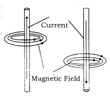

Fig: Magnetic field lines
Let a current-carrying conductor be suspended vertically and the electric current is flowing from south to north. In this case, the direction of the magnetic field will be anticlockwise. If the current is flowing from north to south, the direction of the magnetic field will be clockwise.
The direction of the magnetic field, in relation to the direction of electric current through a straight conductor, can be depicted by using the Right-Hand Thumb Rule. It is also known as Maxwell’s Corkscrew Rule.
Right-hand curl rule (Straight wire): When an electric current passes through a straight wire. Here the thumb points in the direction of the conventional current (from positive to negative) and the fingers point in the direction of the magnetic lines of flux


Fig: Right-hand curl rule (Straight wire)
Magnetic field lines due to a current through a circular loop
In the case of a circular current-carrying conductor, the magnetic field is produced in the same manner as it is in the case of a straight current-carrying conductor. In the case of a circular current-carrying conductor, the magnetic field lines would be in the form of iron concentric circles around every part of the film’s periphery of the conductor. Since, magnetic field lines tend to remain closed when near to the conductor, the magnetic field would be stronger near the periphery of the loop. On the other hand, the magnetic field lines would be distant from each other when we move towards the centre of the current-carrying loop. Finally, at the centre, the arcs of big circles would appear as a straight line.


Fig: Magnetic field lines due to a current
The direction of the magnetic field can be identified using Right Hand Thumb’s Rule. Let us assume that the current is moving in an anti-clockwise direction in the loop. In that case, the magnetic field would be in the clockwise direction, at the top of the loop. Moreover, it would be in an anti-clockwise direction at the bottom of the loop.
Right-hand curl rule (Solenoid)
When an electric current passes through a circular coil or solenoid resulting in a magnetic field. When you wrap your right hand around the solenoid with your fingers in the direction of Convention current, your thumb points in the direction of the magnetic north pole.


Fig: Right-hand curl rule (Solenoid)
Magnetic field and number of turns of coil: The magnitude of the magnetic field gets summed up with the increase in the number of turns of the coil. If there are ‘n’ turns of the coil, the magnitude of the magnetic field will be ‘n’ times of the magnetic field in case of a single turn of the coil.
The strength of the magnetic field at the centre of the loop (coil) depends on:
(i) The radius of the coil: The strength of the magnetic field is inversely proportional to the radius of the coil. If the radius increases, the magnetic strength at the centre decreases
(ii) The number of turns in the coil: As the number of turns in the coil increase, the magnetic strength at the centre increases, because the current in each circular turn is having the same direction, thus, the field due to each turn adds up.
(iii) The strength of the current flowing in the coil: As the strength of the current increases, the strength of the three magnetic fields also increases.
Electromagnetic Induction: Michael Faraday, an English Physicist is supposed to have studied the generation of electric current using a magnetic field and a conductor. Electricity production as a result of magnetism (induced current) is called Electromagnetic Induction.
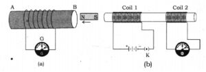

Fig: Electromagnetic Induction
When a conductor is set to move inside a magnetic field or a magnetic field is set to be changing around a conductor, electric current is induced in the conductor. This is just the opposite of the exertion of force by a current-carrying conductor inside a magnetic field. In other words, when a conductor is brought in relative motion vis – a – vis a magnetic field, a potential difference is induced in it. This is known as electromagnetic induction.
Right-Hand Thumb Rule: It is also known as the electrification rule. Induction in generators can be applied during electrification. Here, too, the index, middle, and thumbs of the right hand are perpendicular to each other, and if there is a magnetic field in the direction of the index finger (FLUX) and the motion of the conductor in the direction of the big toe, then there is an electric current generated by the generator in the direction of the middle finger.


Fig: The right-hand rule of Fleming
Fleming Left Hand Rule: If the index, middle, and thumb of the forefinger are perpendicular to each other, and there is an Electro-Motive Force (EMF) in the direction of the middle finger and Magnetic Field (FLUX) in the direction of the index finger, the machine will move in the direction of the thumb.


Fig: The Left-hand rule of Fleming
Electric motor:
An electric motor is a device that converts electrical energy to mechanical energy. It is of two types: AC and DC Motor. Electrical energy is converted into mechanical energy by using an electric motor. The electric motor works on the basis of the rule suggested by Marie Ampere and Fleming’s Left Hand Rule.
Principle of Electric Motor: When a rectangular coil is placed in a magnetic field and a current is passed through it, a force acts on the coil, which rotates it continuously. With the rotation of the coil, the shaft attached to it also rotates.


Fig: Electric Motor
Construction: It consists of the following parts:
- Armature: It is a rectangular coil (ABCD) that is suspended between the two poles of a magnetic field.
- The electric supply to the coil is connected with a commutator.
- Commutator or Split – ring: Commutator is a device that reverses the direction of the flow of electric current through a circuit. It is two halves of the same metallic ring.
- Magnet: Magnetic field is supplied by a permanent magnet NS.
- Sliding contacts or Brushes Q which are fixed.
- Battery: These are consist of a few cells.
Working: Current in the coil ABCD is enters from X and flows back to the battery through brush Y. Current in the arm AB of the coil flows from A to B. In arm CD current flows from C to D. i.e. opposite to the current in the arm AB.
On applying Fleming’s left-hand rule to both the arms we find that the force achieving on arm AB pushes it downwards while the force achieving on the arm CD pushes it upwards. Thus the coil and axel O rotate 1800 about an axis in the anti-clockwise direction.
After the 1800 anti-clockwise rotation, the current in the coil gets reversed and flows along the path DCBA. A device that reverses the direction of the flow of current through a circuit is called a Commutator.
In electric motors, the split ring acts as a commutator. Thus reversal of current also reverses the direction of force acting on the two arms AB and CD. Thus the arm AB of the coil that was earlier pushed down is now pushed up and the arm CD previously pushed up is now pushed down. Therefore the coil and the axle rotate half a turn more in the same direction. the reversing of the current is repeated at each half rotation, giving rise to a continuous rotation of the coil and the axle.
The commercial motors use
- An electromagnet in place of a permanent magnet
- A large number of turns of the conducting wire in the current-carrying coil and
- A soft iron core on which the coil wound. The soft iron core on which the coil is wound plus the coils are called an armature. This enhances the power of the motor

